Introduction
The goal was to build a Raspberry Pi based game emulator running RetroPie, housed inside an original Gameboy case. I also wanted to be able to use it as both a handheld and be able to plug it in to an external display with USB controllers. Other must haves were using a full size Raspberry Pi 3 (not a Pi Zero as I wanted enough power to play N64 & PS1 games), while retaining as much of the original look and feel as possible (which meant no extra visible buttons). Nice to haves were retaining the original battery compartment, and on/off switch. I was willing to give up the built-in speaker as I’d be using headphones whenever using it as a Gameboy.
I spent a bit of time looking around online at other incarnations, and have borrowed ideas from a lot of them. I’ve broken this guide into two parts, hardware & software, rather than mixing them together. In reality you’ll likely be carrying out steps from both at the same time if you wish to build your own.
Gameboy running Zelda - Ocarina of Time N64
Hardware
The Case, the Pi, and the LCD
I started by spending some time toying with different layouts to try and work out the most optimal way to get everything to fit. I decided I ideally wanted to fit the Pi with the attached LCD screen across the top of the Gameboy. After spending some time with both a ruler and my eyecrometer, I was reasonably confident I could make it fit by trimming down both the case and the Pi itself.
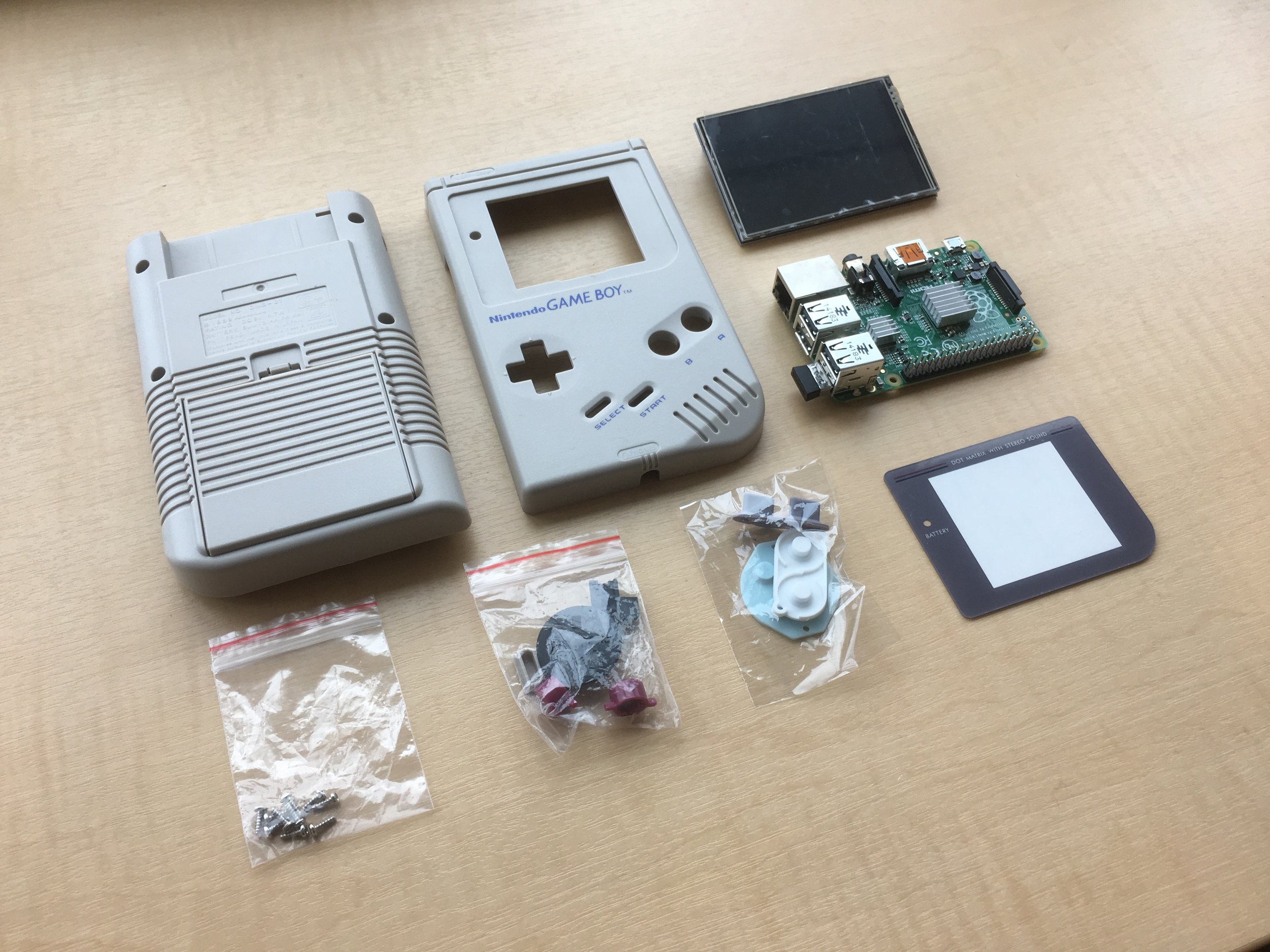
The basic components
By laying it out this way, I could easily expose the USB and LAN ports on the side of the case where the original link cable port and volume control dial were. I would also have space to retain the original battery compartment, and have plenty of space to run internal wiring and expose the composite port. The composite port would double as a headphone port when in Gameboy mode, and a port to run composite video and audio when using it as a console.
I started by modifying the front part of the Gameboy case with a Dremel and files to remove basically everything I could inside the case above the middle 2 screw holes. I also widened the hole for the LCD as I was going to take advantage of the LCD being a lot bigger than the original. I’ve since decided to go with the original Gameboy bezel for the screen, as I can still get a decent resolution with the original screen size, and it looks much more authentic. I then measured the width of the USB/LAN ports on the Pi and cut these out with the Dremel, and finished it with some small files and then wet and dry sandpaper. I had to take a lot of plastic out of the corners of the case to make the screen fit.
Fitting the LCD in the front of the Gameboy case
The back of the case was essentially the same process, and the only other hole in the case I needed to make was for the micro SD card. After I had removed as much as possible from the case I still needed to remove some meat from the Pi itself in order to make it fit. I set to work with the Dremel again trimming down the sides of the Pi until finally it fit with less than a millimetre to spare.
Modifying the side of the Gameboy to make room for ports
Filing down the Pi to make it fit
To finish off the case I got a reproduction blank game case that I cut up and glued to the Gameboy case.
Modifying a reproduction cartridge
The Controls
For the controls, I ordered an aftermarket button board made by a company called Kitsch Bent. After the LCD screen I still had just enough GPIO pins left for the original Gameboy buttons. If you decide to add more buttons to your project just be aware that you will quickly run out of spare GPIO pins and may need to go down another road (a popular option is something called a USB teensy board).
Wiring the ribbon cable to the control board
By using a 10pin ribbon cable, and cutting off the end then soldering that to the button board I managed to keep it very tidy and take up minimal space. Before soldering the ribbon cable to the control board, look at the GPIO pinout and ensure you solder the ground to the ground, and the button pins free GPIO pins. I also had to use the Dremel to remove some meat from the ribbon cable header to make it fit, if you plug it into the end of the GPIO pin row and then try and attach your LCD you will see what I mean.
10-pin Ribbon Cable
Power
Powering the Gameboy involved 3 main components and a bunch of soldering. The components being the USB power controller board, the batteries, and the power switch. The power board itself has 2 separate functions, the first being an input to charge the batteries (which are 3.7v), and then an output that boosts voltage up to 5v. These boards can be brought separately but I settled on a single dual purpose unit that could take in a 5v charge, step it down to 3.7v for the batteries, and then output back up to 5v. This board also required some modification to make fit, firstly to clear the button board, secondly to remove the USB ports which were surplus to requirements, and finally to remove the indicator LED. Somehow the hole in the charging board lined up perfectly with where it needed to be for the case screw. That was more down to luck than planning. One final thing was drilling some holes in the case through to the battery box so the power board would fit in there.
Powering the Pi off a single 3.7v Li-on battery
Test fitting the power board and control board
Next up was the batteries. After doing some investigation I found that you could get Lithium Ion batteries that were the same size as your traditional AAs. These are known as 14500s in Lithium battery naming convention as they are approximately 14mm wide by 50mm long. I went for 4x 2500mAh batteries which should provide plenty of juice.
The case I brought came with the plastic switch cover itself, but I needed a small slide switch to connect it to. I worked out that I could mount a switch on the top of the plastic block that connected the LCD to the GPIO pins. The switch would need to be 5mm high, have a 3mm wide stick, and have 8mm of slide from edge to edge. I ended up finding a 3-position switch that looked suitable. I lined this all up, packed it with Sugru, and then left to set overnight.
Switch mounted in place with Sugru
Connecting it all together consisted of soldering wires to the bottom of the Pi as there was no space to plug a cable in, this was then wired in a single circuit to the switch and the now exposed points on the USB board where the ports were removed. The other side involved wiring the batteries to the USB board. I also needed to add some new battery terminals to the battery box, and as the original Gameboy had the batteries wired in series, these needed to be swapped.
Battery box wiring, converted from series to parallel
Power board with ports removed and wired to the battery box
External AV Port
I initially wanted to use the HDMI out with a ribbon cable to move the port to the outside of the Gameboy case. I couldn't get the cable to work properly with the various angle adapters I needed, so gave up and settled on using the composite video out. To do this, I used a 10cm extension cable that went out of the AV jack on the Pi to the existing hole in the side of the Gameboy that was originally for power. I initially wanted to use the original power port for power and the original headphone jack for AV, but there just wasn’t space up there for the USB controller so I compromised. The port on the extension cable was stripped back with the Dremel, then super-glued to the Pi and reinforced with some Sugru. I was a little hesitant supergluing directly to the Pi board but it seems to be fine.
AV port super-glued to the board and pressed into the side of the case
Port reinforced with Sugru
Software
Installing RetroPie
RetroPie is an awesome project that provides a ready to go disk image for the Pi that is already running all the emulators, and depending on the nature of your build it may require no further configuration. The following steps will show you how to setup an SD Card running the latest RetroPie.
- Download RetroPie Image from the website https://retropie.org.uk
- Download Win32DiskImager from https://sourceforge.net/projects/win32diskimager/
- Insert the SD card into the computer, open Win32DiskImager and select the image file and the SD card, then hit write.
- Put the SD Card into the Pi, plug in Ethernet, HDMI, LCD Screen, and a USB Keyboard if you like.
- Plug in the power and the Pi should boot up, do some automatic setup and then launch into RetroPie. The LCD screen won’t be displaying but the HDMI output should be.
- If you plugged in a keyboard it should have detected it and you can follow the onscreen instructions to configure it.
- You can now start configuring the Pi, the easiest way is through downloading a tool called Putty from http://www.putty.org/ and using it to SSH into your Pi from another computer on the network. It is basically just a way to configure the Pi remotely through the command line. You can find out the IP address of the Pi through the interface on RetroPie.
Configuring the LCD
I chose an LCD screen that plugs straight into the GPIO pins on the Raspberry Pi. I initially tried a 3.5” screen but the refresh speed was terrible to the point most games we unplayable. I then moved down to the 3.2” which worked perfectly at full speed. Your results may vary and this method is only relevant if doing the same. If you are using a screen that uses one of the other display ports then you will need to find another guide for this part, there are plenty online. To do all configuration I used a free tool called Putty which enabled me to SSH into the Pi from my PC. The following will show you how to get the image outputting to the LCD screen. Big thanks to the RetroPie forums for instructions on how to do this (original forum post is here: https://retropie.org.uk/forum/topic/295/retropie-and-waveshare-32b).
1. SSH into the Pi using the default username pi and the default password raspberry.
2. Download the LCD overlays with the following command:
git clone https://github.com/swkim01/waveshare-dtoverlays.git
copy the overlay to the boot directory
sudo cp waveshare-dtoverlays/waveshare32b-overlay.dtb /boot/overlays/waveshare32b.dtbo
3. You now need to edit the config file using a command line text editor called nano. Do this with the following command:
sudo nano /boot/config.txt
This will have opened the config file for editing, scroll down in the file and add these 2 lines to the very bottom of the file:
dtparam=spi=on

dtoverlay=waveshare32b:speed=82000000,fps=60
Hit Ctrl+X to exit, and confirm save by pressing Y then Enter
4. You now need to reboot the Pi to put the new boot settings into effect. Do this with the following command:
sudo reboot
This will kill your connection in Putty, so once the Pi has rebooted you will need to reconnect.
5. Once rebooted we need to check our LCD screen has been detected. Cross your fingers and run the following command:
ls /dev/fb*
If it worked you should see:
/dev/fb0/dev/fb1
With fb0 being the HDMI and fb1 being the LCD. If this didn’t work you may need to find an overlay for your specific LCD screen.
6. Now that the LCD is detected we need to output to it. To do this we will use a tool called rpi-fbcp which will mirror the framebuffer from the HDMI to the LCD screen. To install this enter the following commands, some may take a while:
sudo apt-get install cmake

git clone https://github.com/tasanakorn/rpi-fbcp

cd rpi-fbcp/

mkdir build

cd build/

cmake ..

make

sudo install fbcp /usr/local/bin/fbcp
Once installed we need to configure rpi-fbcp to launch on boot. This can be done by entering the following command to edit the rc.local file:
sudo nano /etc/rc.local
and adding the following just above the line with exit 0 on it
/usr/local/bin/fbcp &
Hit Ctrl+X to exit, and confim save by pressing Y then Enter
7. It’s now time to reboot and hope the LCD comes to life:
sudo reboot
Display Settings
Once the LCD is up and running we’ll need to change where the screen actually renders out on the LCD to line up with the Gameboy case. I’m using the sizing of the original Gameboy screen on mine but you may wish to modify the case to take advantage of having the bigger LCD in there. We’ll also need to make a slight change to enable video output on our composite AV port.
1. To change the viewport we need to head back and edit the boot config again. Do this with the following command
sudo nano /boot/config.txt
2. Once in here we need to adjust the overscan numbers. The numbers below are what worked for my original size screen. The lines should already be in the config, you will just need to uncomment them by removing the # at the start of the line, and then changing the numbers.
overscan_left=60

overscan_right=60

overscan_top=40

overscan_bottom=0
3. To enable the video output on the composite port, add the following line anywhere in the boot config:
sdtv_mode=2
4. Hit Ctrl+X to exit, and confirm save by pressing Y then Enter
Setting Up The Buttons
To setup the buttons we need to use a little utility called Retrogame. This uses the GPIO pins as a virtual keyboard input, and enables us to map the GPIO pins connected to our buttons. More information can be found at https://learn.adafruit.com/retro-gaming-with-raspberry-pi/adding-controls-software
To setup Retrogame, enter the following commands.
cd

curl -O https://raw.githubusercontent.com/adafruit/Raspberry-Pi-Installer-Scripts/master/retrogame.sh

sudo bash retrogame.sh
This will launch the setup utility. Select 1 and press enter, then press Y to reboot. The option you select here doesn’t matter too much as we will manually update the button mapping anyway.
Once rebooted enter the following command to edit the Retrogame config, where we can manually map out buttons.
sudo nano /boot/retrogame.cfg
Map the keys to the GPIO pins by comparing your GPIO pin numbers (which can be found here: https://www.raspberrypi.org/documentation/usage/gpio/) to the buttons they are connected to.
Further Configuration
If you’ve got this far then you’re doing pretty well. Depending how you want to use your Gameboy you might want to plug in some USB controller pads. There are plenty of guides already online that will show you how to do this so I won’t bother repeating that here. You may also want to tweak the resolutions of individual emulators, and the font sizes in EmulationStation. Again, Google is your friend here.
Parts
Raspberry Pi 3b (US $37.88)
3.2” LCD Display (US $12.36)
Reproduction Gameboy Case (US $14.66)
Micro SD Card 64GB (US $25.70)
DMG Common Ground Control Panel (US $11.75 + Shipping)
http://store.kitsch-bent.com/product/common-ground-dmg-button-pcb
Gameboy Game Cart (US $5.99 for 6)
https://www.aliexpress.com/item/Game-Cartridge-Replacement-Plastic-Shell-For-GB/32676191136.html
3.5mm 10cm extender (US $2.99)
5V 2.1A Power Bank Charger Module (US $2.95)
4x 2500mAh Li-ion 14500 Batteries (US $10.21)
10pin 20cm ribbon cable (US $1.16)
Power Switch (US $2.47 for 10)
Battery Terminals (US $3.92 for 18)
Sugru (UK £15.54)
Wiring (US $2.37 for 20 sets)